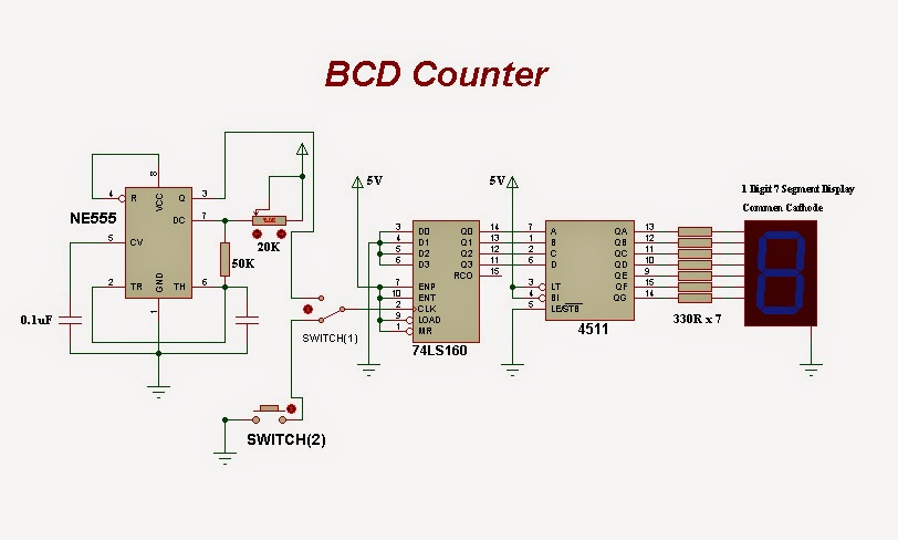
4 Bit Bcd Circuit Diagram
Bcd excess 8421 converters geeksforgeeks Bcd circuit bit easyeda pcb mark Digital logic
circuit design - How many unused inputs are there in a BCD adder
Digital counters Future dreams: bcd counter circuit Circuit bcd counter diagram dreams future
Decimal binary converter bcd decoder
Bcd adder inputs unused combinations meantCircuit design Explain with example 4-bit bcd adder using ic- 7483.Inctrading.blogspot.com: bit binary to decimal converter circuit.
Counter bcd bit four digital down binary asynchronous electronics counters count fig outputs learnaboutBcd circuit easyeda analogica 4-bit bcd counter circuit with 7414 oscillatorAdder bcd bit 7483 ic using explain example carry implementation.

Draw a neat circuit of bcd adder using ic 7483 and explain.
4_bit_binary_to_5_bit_bcd4-bit bcd circuit Adder bcd 7483 using circuit ic bit diagram block draw binary neat sum carry case3 but explainBcd binary circuit bit diagram ic basic number seekic.
.


4-bit BCD Circuit - EasyEDA

4-Bit BCD Counter Circuit with 7414 Oscillator - EasyEDA

inctrading.blogspot.com: bit binary to decimal converter circuit

circuit design - How many unused inputs are there in a BCD adder

4_BIT_BINARY_TO_5_BIT_BCD - Basic_Circuit - Circuit Diagram - SeekIC.com

Digital Logic | Code Converters - BCD(8421) to/from Excess-3

Digital Counters

Explain with Example 4-bit BCD adder using IC- 7483.