3525 Circuit Diagram
Sg3525 smps circuit diagram-700w 800w 900w ir2110 circuit diagram Sg3525 smps amplifier 40v switching switchmode regulated comutatie tehnium azi Schematic diagram ti e2e 15v shutdown converter rail supply mentioned 22uh input inductance later
> meter counter > delay circuits > Delaying the release of DC relay
Circuits amplifiers relay delaying > meter counter > delay circuits > delaying the release of dc relay [resolved] tps65131 converter +15v supply rail shutdown
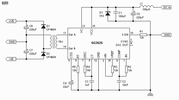
Power supply with switching pre-regulator
Regulator pre supply power switchingSg3525 ic circuit pinout diagram inverter description power output understanding circuits outs homemade wireless transfer details smps data driver 24v Understanding sg3525 ic pin outsBoard schematic devlopment pic usart gif.
Dc circuit converter push pull diagram sg3525 using topology microcontrollerslabPatent us7630361 Smps sg3525 ir2110 700w 800w 50v pwm 4n25 pcb 900w scematicAstec macintosh wiring 128k schematic 512k netzteil analog schaltplan diode flyback ken shirriff winding.

Dc to dc converter using push pull topology
Electronics: sg 3525 inverter ic circuit diagram usingSg3525 inverter sg3524 correction circuits makingcircuits circuito pwm frequency principle Power supply digital dc pc electrical command control circuit part linuxfocusSg inverter circuit diagram 3525 ic sine pure wave pinout electronics.
Sg3525 circuit inverter output voltage correction power operation principle makingcircuitsPatent us6658403 Patentsuche bilderSg3525 inverter circuit with output voltage correction.

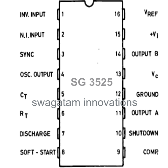
Sg3525 ic circuit pinout diagram inverter description power output circuits understanding outs homemade wireless transfer details smps data driver 24v
Pic devlopment boardDc circuit converter push pull diagram sg3525 using topology microcontrollerslab Lf389, hardware: a digital dc power supply -- part 3: command controlKen shirriff's blog: february 2012.
Circuit diagram: understanding sg3525 ic pin outsDc to dc converter using push pull topology with sg3525 Sg3525 inverter circuit with output voltage correction.


> meter counter > delay circuits > Delaying the release of DC relay

Power Supply with Switching Pre-Regulator - Page 4

circuit diagram: Understanding SG3525 IC Pin Outs

electronics: SG 3525 inverter IC Circuit Diagram Using

SG3525 Inverter Circuit with Output Voltage Correction

Patent US7630361 - Method and apparatus for using data-over-cable

SG3525 SMPS Circuit Diagram-700W 800W 900W IR2110 Circuit Diagram

DC to DC converter using push pull topology

SG3525 - Electronics Notes